
 “Financial Product”WeChat
 “Telecommunication Product”WeChat
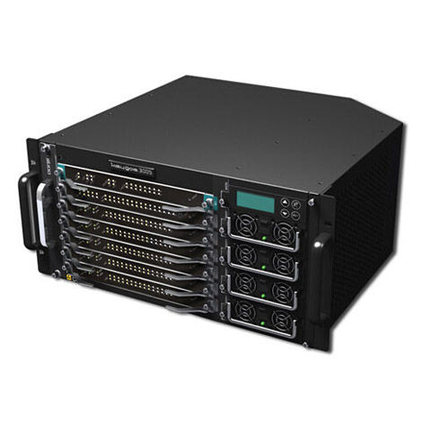


DONJIN Digital Cross-Connect Device
DONJIN digital cross-connect (DXC) device is a kind of telecom-level device based on the timeslot cross connections. It provides a maximum of 64 standard E1 interfaces for timeslot cross connections between the 64 kbps and n*64 kbps. It is widely used in the services which use multiple E1 circuits for networking, such as the SS7 link grooming and detection for the missed call notification service in fixed lines, multi-service access points based on the E1 transmission, user switch timeslot grooming in a private network, and DDN or ATM node device E1 interface expansion. The device can optimize the network structure, reduce channel costs, and improve the transmission efficiency.
 Download
 l Powerful cross-connection capacity, providing timeslot cross connections between the 64 kbps and n*64 kbps; the maximum timeslot cross-connection capability is 4096×4096.
l With clear configuration interface and simple operations
l The E1 interface confirms to the ITU-T G.703, G.704, G.732N, and so on.
l The DXC device provides multiple loop test functions, convenient for system maintenance.
l After power-off, the device could continue working without being reconfigured.
l Sending clock could use any internal E1 port to recover the clock.
l The modularization structure could expand the capacity linearly from 4 E1s to 64 E1s.
l The users could operate on the device manually without using any tool.
l The digital timeslot cross interface board has the function of hot swapping.
l The link timeslot status, device temperature, power status, and fan rotation speed could be detected and alarmed.
l Provide 2 or 4 system power supplies for redundancy to improve the device stability and reliability.
l The modules and power supplies have independent air passages; the device could be adapted to a wide environment humilities and temperatures.
l The electromagnetic shielding function reaches the E level.


Read and display the E1 board configuration count and slots.
Add, delete, configure, save, and read the configuration files.
Set and read the test information of each E1.
Set the E1 hardware interface configuration.
Read any usable E1 as the clock.
Check the static and dynamic states of each E1.
Display and update the firmware version of the current board.
Add new cross connections one by one or in batches.
Delete the current cross connections one by one or in batches.
Read all the cross connection settings to the device.
Write all the cross connections in a configuration file.
Type | Digital Timeslot Cross Interface Board Count | E1 interface count | Timeslot cross connection capacity* |
PEMSDXC162 | 1 | 16 E1s | 512×512 |
PEMSDXC322 | 2 | 32 E1s | 1024×1024 |
PEMSDXC482 | 3 | 48 E1s | 2048×2048 |
PEMSDXC642 | 4 | 64 E1s | 4096×4096 |
*This parameter indicates the device timeslot input/output capacities. Take PEMSDXC162 as an example, it supports 512-timeslot input and 512-timeslot output.
1. Timeslot cross capacity
l Support one channel crossed to multiple channels in a device. A maximum of 64*31 channels can be crossed to one channel.
2. E1 interface
l Conform to the G.703, and support the coaxial cable (75 Ω unbalanced), twisted-pair cable (120 Ω balanced);
l Conform to the frame structure of G.704 and multiframe alignment of G.706;
l The 2048 kbps PCM confirms to the G.732 and G.796;
l The CRC4 multiframe alignment is self-adapted.
l The CCS and CAS are compatible. For the CAS channel, the E1 interface could transmit data transparently to the TS16.
l The line code pattern is HDB3.
l The jitter and wander conforms to the G.823.
3. System clock
l The clock could be synchronized to any E1 clock in the chassis.
4. Environment Requirement
l Temperature: 0°C–55°C;
l Relative humidity: 10%–85%
l Air cleanliness: For the dust particle which diameter is more than 0.5 μm, the density cannot be over 3500 particles per litre. For the dust particle which diameter is more than 5 μm, the density cannot be over 30 particles per litre. Avoid excessive dusts, velveteen, carbon powders, paper fiber sundries, metal sundries, and corrosive gases such as sulfur and chlorine
l Electromagnetic environment: Electric field strength≤130 dB (μV/m); magnetic field strength≤800 A/m
l Anti-Static: The device is grounded reliably.
5. Grounding Requirement
l The grounding resistance is less than or equal to 1.5 Ω.
6. Installation Mode
l Installed in a standard 19" rack;
l The rack need be fixed to the floor;
l The rack need be fixed by the front panel or the middle.
SS7 Grooming
The value-added services based on the SS7, such as the CRBT, missed call notification, and roaming service, need collect and analyze a large amount of SS7 links. The fact is that most of the low speed SS7 links exist in various E1 lines, and the signaling timeslots are scattered, which makes the service operation not only difficult but also with high costs. By DONJIN DXC devices, the various timeslots of the SS7 uplinks and downlinks in various E1 lines can be groomed to one or several E1 lines, which not only decrease the transmission lines and improve the transmission efficiency, but also reduce the service costs.
